Packet Tracer STP Configuration
In this post, instead of detaily talk about
STP (Spanning Tree Protocol), we will focus on a basic
Switching Loop topology and how
STP mechanism helps to avoid this Switching Loop.
You can
DOWNLOAD the
Packet Tracer example with
.pkt format
HERE.
Switching Loop is an unwanted problem in a network. Then, what is Switching Loop?
Switching Loop is the situation, in which there are two
layer 2 path between two layer 2 endpoint(switch, brigde). Switches creates broadcast storms from every port and switch rebroadcast again and again. Because of teh fact that there is no
TTL(time to live) mechanism on layer 2, this continues forever.
To avoid this unwanted
Switching Loops, there are some mechanisms. One of the most common name of this mechanisms is
STP(Spanning Tree Protocol).
Acording to this protocol, in the switching topology, a
Root Bridge is selected. And then the connected port of the switches are classified. The port classification and their meaning are like below:
– Root Port : The port to the Root Bridge
– Designated Port : The other port thatis not Root Port
– Non Designated (Blocked) Port : In a segment, other port than the Designated Port
The selection process is done orderly. First
Root Bridge is selected, secondly
Root Ports on all the switches, then
Designated Ports are selected, and lastly the remainning ports become
Non-Designated Port, meaning
Blocking Port.
STP Example on Packet Tracer
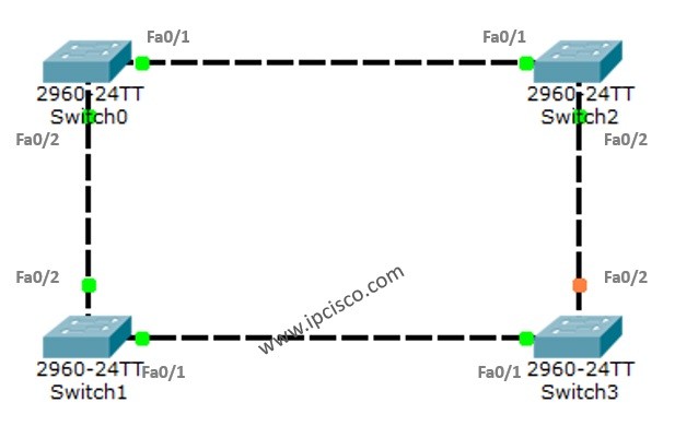
For STP example with PAcket Tracer, we will use the below switch topology.
 Example Topology on Packet Tracer") STP Example Topology
STP Example TopologyAs you can see after connecting the switches together in the Loop position, one of the ports become blocking. Because by default STP is enabled and it is avoiding us any Switching Loop.
To understand more detailly let’s check the show screenshots.
On Switch0
Switch0#show spanning-tree
VLAN0001
  Spanning tree enabled protocol ieee
  Root ID    Priority    32769
             Address     0001.C90E.EDC0
             This bridge is the root
             Hello Time  2 sec  Max Age 20 sec  Forward Delay 15 sec

  Bridge ID  Priority    32769  (priority 32768 sys-id-ext 1)
             Address     0001.C90E.EDC0
             Hello Time  2 sec  Max Age 20 sec  Forward Delay 15 sec
             Aging Time  20

Interface        Role Sts Cost      Prio.Nbr Type
---------------- ---- --- --------- -------- --------------------------------
Fa0/1            Desg FWD 19        128.1    P2p
Fa0/2            Desg FWD 19        128.2    P2p
Switch0#show spanning-tree active
VLAN0001
  Spanning tree enabled protocol ieee
  Root ID    Priority    32769
             Address     0001.C90E.EDC0
             This bridge is the root
             Hello Time  2 sec  Max Age 20 sec  Forward Delay 15 sec

  Bridge ID  Priority    32769  (priority 32768 sys-id-ext 1)
             Address     0001.C90E.EDC0
             Hello Time  2 sec  Max Age 20 sec  Forward Delay 15 sec
             Aging Time  20

Interface        Role Sts Cost      Prio.Nbr Type
---------------- ---- --- --------- -------- --------------------------------
Fa0/1            Desg FWD 19        128.1    P2p
Fa0/2            Desg FWD 19        128.2    P2p
As we can see above, the addresses are for the Root and the Bridge part. So, Switch0 is selected as
Root Bridge. The Root Bridge is selected according to the Bridge ID, The Bridge ID is the MAC address of the Switch. So, the lower one is selected as Root Bridge. This is Switch0.
The two port of Switch0 are normally Designated Port. Because all the ports on Root Bridge is always choosen as
Designated Port.
Both of these ports are in Forwarding State, this means that they are ready to send the traffic. As a recall, as you know there are four states of an STP port. These are:
– Blocking (20 seconds)
– Listening (15 second)
– Learning (15 second)
– Forwarding
You can also use the following commands to check the spanning-tree information.
Switch0#show spanning-tree interface fa0/1
Vlan             Role Sts Cost      Prio.Nbr Type
---------------- ---- --- --------- -------- --------------------------------
VLAN0001         Desg FWD 19        128.1     P2p
[sc name=”ContentRMessage”]
You can check the other Packet Tracer Examples below:
Common Cisco Router Configuration Example on Packet Tracer
Router DHCP Configuration Example on Packet Tracer
VTP Configuration Example on Packet Tracer
VLAN Configuration Example on Packet Tracer
STP Configuration Example on Packet Tracer
RSTP Configuration with Packet Tracer
STP Portfast Configuration with Packet Tracer
Inter VLAN Routing Configuration on Packet Tracer
Switch Virtual Interface (SVI) Configuration with Packet Tracer
BGP Configuration Example on Packet Tracer
Port Security Configuration Example on Packet Tracer
RIP Configuration Example on Packet Tracer
CDP Configuration Example on Packet Tracer
OSPF Area Types Example on Packet Tracer (Standard and Backbone Areas)
OSPF External Routes Example on Packet Tracer
OSPF Area Types Example on Packet Tracer (Stub, NSSA, Totally Stubby, Totally NSSA Areas)