PVST+ Configuration on Packet Tracer
In this Spanning Tree Configuration Example, we will configure STP with
STP Mode PVST+. As you know,
Per VLAN STP Plus is the STP Mode that uses one
STP instances per VLAN.
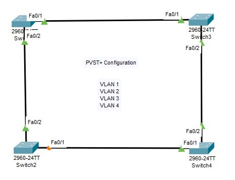
For this
Configuration Example, we will use the below switch topology.
We will do the below configuration steps for our
PVST+ Configuration on
Cisco Packet Tracer.
1. Defining VLANs on the swithes (VLAN 1,2,3,4)
2. Setting all switch interfaces as Trunk and se tthe allowed VLANs
3. Setting STP Mode as PVST+
4. Setting VLANs in STP Topology (VLAN 1,2,3,4)
5. Verification
6. PVST+ Manuplation Commands
Defining VLANs on the swithes
We will define VLAN 1,2,3 and for on each switch. VLAN 1 is also defined by default. SO it is not necessary to create it. The below configuration will be done on each switch.
Switch-1#
configure terminal
Switch-1(config)#
vlan 2
Switch-1(config-vlan)#
vlan 3
Switch-1(config-vlan)#
vlan 4
Switch-1(config-vlan)#
exit
Setting all switch interfaces as Trunk
We will configure allt he interfaces between the switches as
Trunk interfaces and we will set the allowed VLANs on these interfaces. Allowed VLANs are our VLANs that we have created before. We will do the same configuration on each switch.
Switch-1(config)#
interface fastethernet 0/1
Switch-1(config-if)#
switchport mode trunk
Switch-1(config-if)#
switchport trunk allowed vlan 1-4
Switch-1(config-if)#
exit
Switch-1(config)#
interface fastethernet 0/2
Switch-1(config-if)#
switchport mode trunk
Switch-1(config-if)#
switchport trunk allowed vlan 1-4
Setting STP Mode as PVST+
We will set the stp mode as PVST on each switch.
Switch-1 (config)#
spanning-tree mode ?
pvst Per-Vlan spanning tree mode
rapid-pvst Per-Vlan rapid spanning tree mode
Switch-1 (config)#
spanning-tree mode pvst
Setting VLANs in STP Topology
After setting the STP Mode, the VLANs in the Per VLAN STP Domain will be defined on each switch like below.
Switch-1(config)#
spanning-tree vlan 1-4
Switch-1(config)#
exit
After the configuration, we will save the configuration on each switch.
Switch-1 #
copy running-config startup-config
Verification of PVST+ Configuration
To verify our Per VLAN STP Plus configuration, we will use the below commands. You can find the outpıuts of some of them to learn PVST+ better.
• show spanning-tree summary
• show spanning-tree
• show spanning-tree vlan vlan-id
• show spanning-tree interface interface
• show spanning-tree detail
Switch-1 #
show spanning-tree summary
Switch is in pvst mode
Root bridge for:
Extended system ID is enabled
Portfast Default is disabled
PortFast BPDU Guard Default is disabled
Portfast BPDU Filter Default is disabled
Loopguard Default is disabled
EtherChannel misconfig guard is disabled
UplinkFast is disabled
BackboneFast is disabled
Configured Pathcost method used is short
Name Blocking Listening Learning Forwarding STP Active
———————- ——– ——— ——– ———- ———-
VLAN0001 0 0 0 2 2
VLAN0002 0 0 0 2 2
VLAN0003 0 0 0 2 2
VLAN0004 0 0 0 2 2
———————- ——– ——— ——– ———- ———-
4 vlans 0 0 0 8 8
[sc name=”ContentRMessage”]